
Lissajous Generator description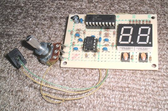
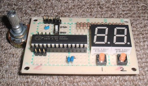
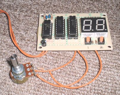
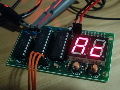
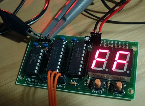
The first trial consists of 1 PIC and OP amp (left photo). This is no good for ugly sine wave form. The second trial consists of PSoC (middle photo). This is good wave form shape but no good for phase changing operation. And, the third trial consists of 2 PICs and DAC (right photo). This is good and we make original PCB along this circuit.
First, we show you the brief description about making this kit with some photos.
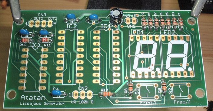
Please start to put and solder short parts first (R and C).
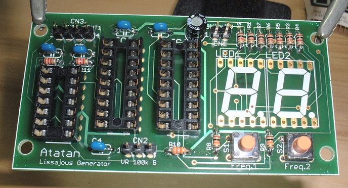
And, put and solder switches and IC sockets.
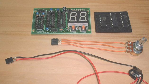
After all parts soldered, make wiring for VR and power supply like this.
(connectors etc. are not included in this kit.)
Last, put ICs to IC sockets slowly. Be careful, for not bend IC pins.
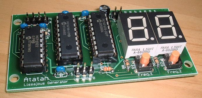
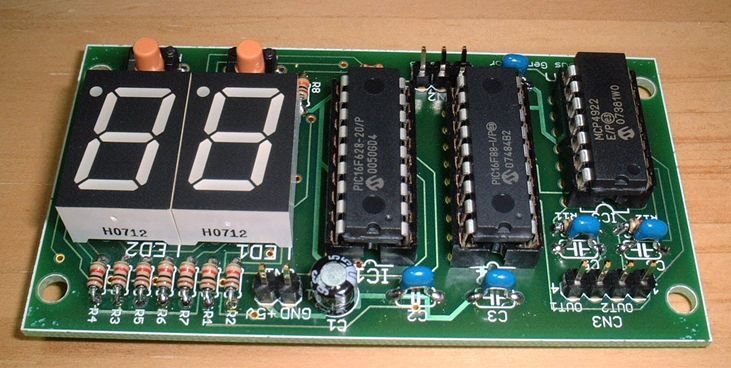
These two photos are at the final stage from front and back. Please confirm parts fixing carefully.
-----
The next is operation waveform.
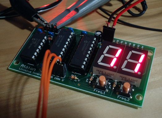
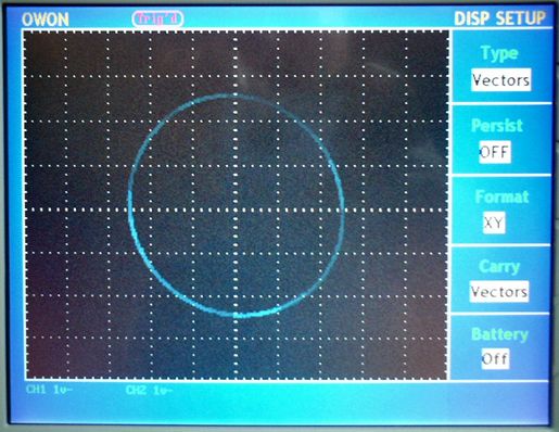
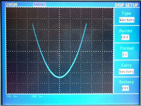
Freq. ratio is 1 : 1.
The phase is adjusted by VR.
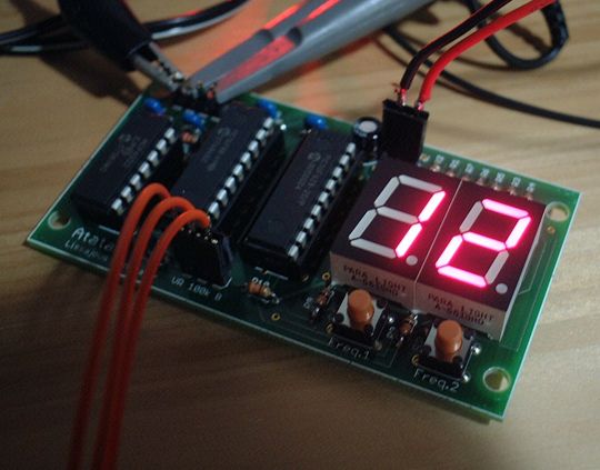
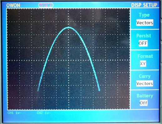
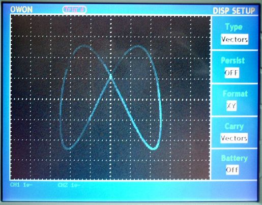
Similarly, freq. ratio is 1 : 2. The phase is changed by VR.
Freq. ratio is 10 : 12.
Frequency goes up, and distortion goes up.

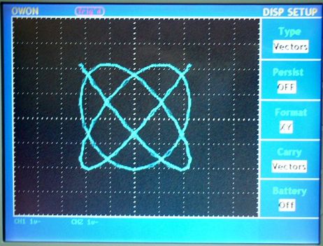
Freq. ratio is 15 : 15.
Because of distortion, the shape is no longer pure circle.
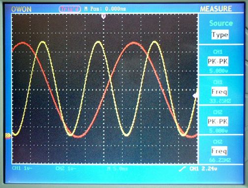
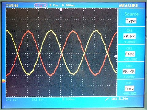
Time domain wave form at freq. ratio 1 : 2 / 15 : 15. There is wave form distortion in the high freq. range. Frequency is 33 Hz at 1 times, and 495 Hz at 15 times respectively.