
Vacuum tubes for beginners
Here's a tale of early '70s vacuum tubes, mainly from the viewpoint of amateur radio.
Number of visitors to this page is
since Jan. 1 1997.
Last update of this page was Jun. 1, 2002.
I'd like to tell you tales of vacuum tubes that we would come across when we used vacuum tubes in the early '70s in Japan.
Principle
A Cathode emits electrons, and a plate receives the electrons from the cathode, it's actually quite simple.
Normally, there is a grid (at least one) between the cathode and the plate. Its purpose is to control current flow through the vacuum. A typical plate voltage is on the order of several hundred volts (+V), and a grid voltage is normally several volts (-V), with respect to the cathode which is referenced at 0 V.
Heater and filament
Most vacuum tubes require a heating element for electron emission from a cathode (except
discharge tubes). This element is called a heater if it is separate from the cathode. It's called a filament if it's used for both heating and for emitting (earlier design). This is the reason why electric circuits using
tubes start slowly - because it takes time for the heater or the filament to warm up sufficiently to emit electrons. BTW "Tube" is an American word. In England they are called "valves" (a contraction of "thermionic valves") because they rely on heat and they can control the flow of current - hence "valve".
Types of tubes
There are roughly 3 kinds of vacuum tube types: the ST tube, the GT tube, and the MT tube. (ST = "Shouldered Tube", GT = "Glass Tube" and MT = "Miniature Tube".)
 |
Circa 1970 in Japan, there was a super-heterodyne radio set that used 5 MT type tubes (referred to as "the All American Five" in the US), or a B/W TV set which was dumped at a garbage dump. The image of type of tubes is shown in the picture on the left. |
Heater voltage
The number code of the tube indicates the heater voltage: for example, 12BY7A is a tube which has a heater operated at 12.6V (not 12 V), and 6 means 6.3 V (not 6 V). These voltages originally came from the days of using lead acid batteries for the power source, since many people did not have any other source of electricity. 6.3 V is the voltage of a fully charged "6 volt" lead acid battery (2.1 volts per cell). 12.6 volts is the voltage for a 6 cell battey such as is used now in all cars (3 cell batteries were used until the late 1950's in the U.S.). This is the reason why we have seen power transformers in the old days with 6.3 V on the secondary windings. The TV or the radio was designed not to use transformer because it is heavy weight (and expensive). I saw dumped radios or TVs in a garbage dumps in '70s in Japan which were designed without transformers. It is a design method for connecting multiple tube heaters in series, and total voltage is matched to the voltage of the power source (100 V in Japan). By using this method, a chassis is not insulated from the power line, and it is very terrible that we will get an electric shock by touching the chassis for a probability of a half, dependent on which way round the power cord is connected ! In Japan, we had a risk of getting a 100 V AC shock, because one of the power lines is grounded. (In the USA, it is safe because there are 3 lines in the terminal that include one ground. However, there is a great amount of two old line wiring out there yet. Nowadays, it is safe because of polarized plugs that by standardization have one Hot line and one Neutral/Return line. The Hot line is the narrow spade on the plug while the neutral is the wide spade. Thanks for the information !) (In the USA, the situation was the same in Japan in old days. I hear that the word "Hot chassis"
comes from the feeling of getting a shock like from something "HOT". In England it's called the "Live" connection because it "bites" as if it were alive.)
I hear that it is a basic technique not only calculating heater voltages but also adjusting heater currents. If a tube is used with no adjusting the current, it's no good. There were 150 mA series (e.g. 12BA6, 35W4, 50C5), 300 mA series, 450 mA series (e.g. 31JS6, 40KD6), and 600 mA series (e.g. 30KD6). For example, two 150 mA tubes parallel connected can be series connected to a 300 mA series tube. But it is not so easy to design real circuit. Transition of resistance of heaters from cold to hot must be matched well (the resistance is smaller when the heater element is cold so there is a surge of current at turn-on).
Tubes used in the "All American Five"
In the USA, "All American Five" consists of 12BE6, 12BA6,
12AV6, 50C5, and 35W4. The heater voltages add up to 121 volts for transformer-less
design. In Japan, it consists of 12BE6, 12BA6, 12AV6, 35W4 (35W4 is a rectifier.)
the same in the USA set about these four tubes. The final tube of the AF
amplifier was 35C5 or 30A5. If a 30A5 is used, the heater voltage becomes
101 V, almost the 100 V that are available in Japan ! I receive the information that it consists of 6WC5, 6D6, 6C6(or 6ZDH3A?), 6ZP1, and 12F (all of ST tubes) for approx. 1W AF output; and 6WC5, 6D6, 6C6, 42, and 80 (all of ST tubes) for approx. 3W AF output in older days around 1955.

Some famous tubes (in Japan)
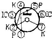
| 0A2 |
This is a discharge voltage regulator tube for regulating a fixed voltage by gas discharge effect.
(The purpose is the same for a zener diode.) I couldn't see it in the 5 tube super-heterodyne radio sets. This kind of tube glows when in use, a nice 'blue-glow' in a darkened room, I hear. |
 |
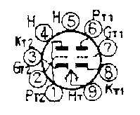
| 12BH7A |
There are lots of this tube in B/W TV sets found in garbage dumps. But I felt that this tube is not for use in normal circuits. This tube is for use in oscillators and voltage amplifiers. This particular tube was not intended to amplify small signals, but despite this it has been used as a pre-driver for KT88 in the famous Machintosh model 275 amplifier, I heard. This tube is also used in most models of Hammond organs from 1955 to 1975. This low-mu double triode is used as a class 'A' single-ended power amplifier (both halves parallel connected for about 3 watts) feeding a reverb spring (Model L-100), 600 ohm line driver (Models B-3, C-3,
RT-3...), and vibrato delay line driver (Models B-3, RT-3...). This tube
was originally designed for oscillator applications in TV sets, and it has been widely used in audio circuits. |
 |
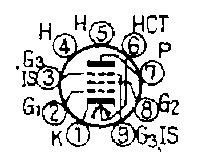
| 12BY7A |
There were many articles for building electronic apparatus
using this tube in some radio magazines. This tube is used commonly as a driving tube before the final for TX for HF band. But it was not often found in the garbage dump, so we had to buy at a radio shop. Originally, this
tube was for a final video amplifier in TV sets. The US version TRIO/KENWOOD TS-530S uses one 12BY7A to drive the two final 6146B tubes. |
 |
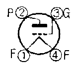
| 2A3 |
There's no need to explain this particular tube because this is a very famous tube for audio fanatics. (I didn't, and don't have this tube
because it is too famous and too expensive to have !?) This is a directly heated triode
using not a heater but a filament. I hear that it is no good to use pentaode
with heater, it's cool to use triode with filament, isn't it ? I'm not
familiar with that..... |
 |
| 2E26 |
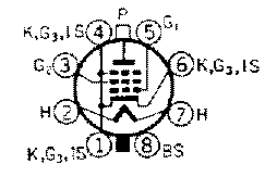
This is a famous tube for use as the final of HF TX in Ham radio. This
tube affords us 10 W output power through all HF bands and 6 m band. (In
Japan in those days, 10 W was a significant amount of output power, as this amount was the limit for novice class operators.) (Nowadays, the max power for
novice is 20 W, I hear.) In the early '70s' sets, a hybrid design that used tubes in the driver and final sections, the rest being solid state, was common.
(e.g. in Japanese rigs, the 2E26 was used by some lots of TRIO TX88A, TX26, TX388,
and Nissin Skyelite 6 which is a famous 6 m AM rig.) |
 |
| 4CX250B |
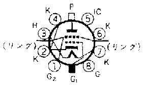
The word "4CX" means directly a linear amplifier
! Many linear amplifiers used this tube to boost HF 10 W TX input from Japanese rigs, I know.
This tube affords us more than 100 W output in HF. But I don't know anyone that has a rig that uses this tube. This tube in Japan was mostly used by wealthy old-timers or under-cover stations. Do you know the meaning of "4CX" ? "4" designates tetrode. "C" means
ceramic insulation, and "X" means externally cooled body, ("W" means water cooled, "V" means vaporization cooled). The next numeric designates the plate loss... but there are exceptions, I hear. This tube is a very coveted tube in the broadcast industry. It is used in many of the commercial, high power tube type radio transmitters as a driver tube for a bigger final tube, such as the 4CX5000A and 4CX15000A. Thanks for the information. |
 |
| 5MK9 |
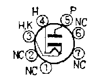
This is a diode. It performs only the same job as a cheap silicon diode.
In a garbage dump, I could find this tube, but it was common to see a semiconductor
diode used in radio magazine articles even in the early '70s. It's a pity that diode tubes are not loved in the same way as the 2A3 triode by audio tube fanatics. |
 |
| 6146/6146B |
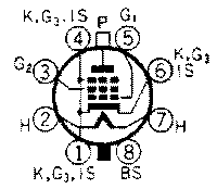
These are famous tubes for transmitters. The 6146B is also called the S2001, The S2001 is a better known tube. (I hear that the S2001 is a lower cost version of the 6146B made for commercial use by Matsushita Electric corp.) (The cost reductions consist of changing the manufacturing material of the base to bakelite, so a shield case is required, and by changing the material of the plate (of different color than the original plate material). Many people wondered whether this one really had the same plate loss as the 6146B, I hear.) These tubes handle not only 10 W in HF - but also 10 W in the 6 m - band. In Japanese HF rigs, the TS311(TX310), and also the 510 from TRIO used this tube. In the early 70's, there was a kit for a 6 m SSB transceiver
and it used the S2001; the model number of this kit is QS500 from TRIO. (Oh, TRIO was Japanese domestic
name for KENWOOD, now it is KENWOOD even in Japan. I receive the information that TRIO was called KASUGA-electric further early days.) (and TS310 and QS500
also use a 12BY7A as a drive tube.) |
 |
| 6AQ5 |
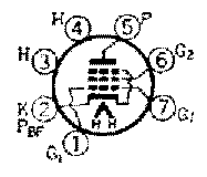
This tube is of the MT type corresponding to a 6V6 GT tube - an AF amplifier
tube. The 6AQ5 is also used as a driver or a final tube for low power TX due in part to its excellent frequency response. By the way, what is the final tube of the FT401S but a 6KD6, isn't it ? I received information that the FT401S uses 6JS6A (or C), FTDX401 uses
two 6KD6's, the FL2500 uses five 6KD6's, and the FL2100 uses two 572B's. The YAESU linear
amplifier (FLDX2000?) uses four 6KD6's. After a shortage of 6KD6, user diverted 30KD6 less expensive one. The heaters are connected serially
for 120V derived from the 120V tap of a power transformer. These information is not sure. It might have been designed in the transformer-less style for the USA model. |
 |
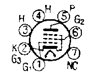
| 6AR5 |
This was a common tube found mostly in the garbage dumps. This is for AF amplifier applications for inexpensive radios, I think. |
 |
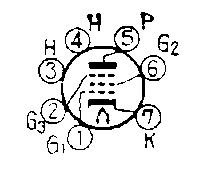
| 6AU6 |
This was a popular tube in radio magazines articles for receivers.
It is an amplifier for RF/IF especially for IF applications. The grid of the 6AU6 is wound with
uniform spacing to produce a sharp cut-off. On the contrary, the 6BA6 grid
is spaced close in the middle and wide at the ends to give a remote cut-off.
|
 |
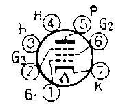
| 6BA6 |
This is a SuperStar tube. It was made very popular in an article found in radio magazines for a 5 tube super-heterodyne radio, ham receiver, and
AM band wireless microphone etc. This is a tube for RF amplifier applications. For remote cutoff applications this tube is probably used in an RF AGC ? I remember somewhat that the 6BA6 is for RF, and the 6AU6 is for IF.... (In the "All American 5" radios, 6BA6 (12BA6 exactly) is used as the IF amplifier.) The grid of the 6AU6 is wound with uniform spacing to produce a sharp cut-off. On the contrary, the 6BA6
grid is spaced close in the middle and wide at the ends to give a remote
cut-off. As mentioned above, the 6BA6 was used as an RF amplifier for non-professional applications (e.g. radio sets). I hear that for RF amplifiers in communication receivers the tube that was used was mainly the 6BZ6. (Furthermore, in case where higher performance was required, the 6DC6 was specified (this was not made in Japan.).) By the way, FM radio was not common in those days in Japan yet, but it was already common in the USA. I receive the information that 6BA6 is used as a limiter before the 6AL5 FM discriminator.
|
 |
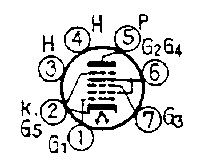
| 6BE6 |
Septode, it's a frequency conversion only. There is always a 6BE6
after a 6BA6. (However, in the "All American 5", 12BE6 is the front end and 12BA6 is the IF amplifier.) This is a mixer that probably operates as an oscillator and mixer in one tube. The first grid acted as a triode input for an
electron-coupled oscillator, with the second grid acting as the plate for
the oscillator. The third grid acted as an input for the mixer, with the
fourth and fifth grids acting as the remainder of the mixer pentode. |
 |
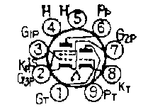
| 6BM8 |
Also very common tube. It's a combination of a triode and a pentode.
In this tube, the triode part works as an audio pre-amplifier that feeds the pentode section which acts as an audio main-amplifier. This is not generally used as a HiFi tube, except for special HiFi versions. I hear that Svetlana currently manufactures a new version that reportedly sounds very nice.
| Recently, this tube is popular for making STC (Super Triode Connection) amplifiers, I learn it now. After I read some articles, I make an amplifier using 6BM8 at last. In detail, please look at this page. |
|
 |
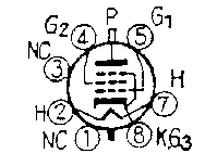
| 6GB6 |
This is a GT type tube, but I don't know what kind of tube this is. Sometimes
I found this tube in TV sets at the garbage dumps, ..... It might be used as a final
tube of the horizontal driver in B/W TV sets. This tube might only be manufactured
in Japan. I heard that this tube is an equivalent for an EL36 which is
used in Europe. There is another tube, the E130L, but it is very expensive.
So people used this one as an inexpensive substitute for the E130L. |
 |
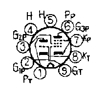
| 6U8 |
This is a higher grade tube than the tube which is used for 5 tube super-heterodyne
radio sets. It's also a combination triode and pentode, but it's for RF amplifier use,
with low noise in the RF bands. In a receiver for communications use, there
are two 6U8: the triode of the first one is an RF pre-amplifier; the pentode
of the first one is an RF amplifier after the triode; a triode of the second
one is used as a local oscillator, and a pentode of the second one is used as a mixer,
I remember. This tube looks fat, short, and pretty. ECF82 is the European code for this tube.
|
 |
| 807 |
Very famous TX tube. The TRIO TX88A (only some lots) use this
tube, but mainly people that do lots of DIY use this tube occasionally. This tube was
popular in the old days before the 70's. In HF bands, about 20 - 50 W output is possible. By
the way, TX tube has a terminal located on the top of the tube. Of course,
it's used mainly in high power applications and it has a good aesthetic design reminiscent of the good old day's. A bit of trivia regarding the 807. American hams, years ago, would enjoy a
"cold 807". This was a reference to a bottle of beer, due to the similar
shape of the 807 tube.
QST Magazine had a picture sent in of a beer called "88" (evidently 8.8%
alcohol). The caption read, "After a couple of these cold 807s, it will be
73."
|
 |
| Magic eye (6MDE1) |
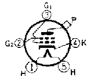
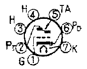
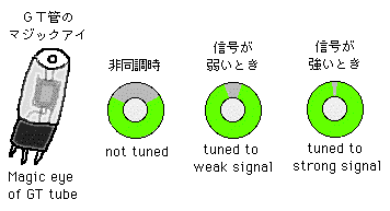
This tube is used for displaying tuning status. There is a band of light that forms a sector, the remaining sector being a shadow. The shadow is wide in the out-of-tune condition. The shadow sector constricts as the signal is being properly tuned, remaining as a slim sector when at maximum tuning. This sketch of terminal connection shows an MT type tube, but this tube was originally a GT type in the super 5 tube receiver found at the garbage dumps. The following figures illustrate the operation of this tube, but it shows an ST type tube in spite of looking like a GT type. This is called a 6E5 (or 6G5 type) perhaps. In the old days, there was no PLL IC and no light emitting diodes. 'S' meters were expensive for standard radios. The figure below is the shape of the green light band. (I hear that the non-bright portion is set on the lower side for installation purposes in a radio case. I cannot confirm this because I only picked one up without a case at the garbage dump.) |
 |
| Nixie tube |
This is an extra, Nixie tube. There are ten electrodes each having digit shape "0123456789" in a short glass container like a vacuum tube. For example, if a voltage is added to "0" digit, shape "0" shines by discharge the same as a neon tube. In last years of the Nixie tube, there was "seven segments" type, but most Nixie tubes were not seven segments but one-to-one connection type. This one-to-one connection makes a Nixie tube having original air. In restriction from this structure, some digit must be hidden by other digits. Therefore, each digit has perspective at countdown event. On a random changing digit operation, perspecitve is randomly changed. It's very interesting. Further, the color is orange-gold like vacuum tube because of neon discharge. It has also original air. Font was also very unique. In those days, this tube was very common. We could see it in many train ticket vending machines for JNR, other lines, and subways in Tokyo. I use the image of a nixie tube in the access counter on this page. This very nice photo was derived from this page. I would like say many thanks to the owner of this page for permission of use it in my page.
|
WWW  WWW WWW |
This page is kept updated by great information from you.
Thanks a lot.
I'm not a native English speaker as you can tell.
Suggestions for corrections are welcome.
I'd like to say a special thanks to Mr. Richard Sherman (KP4FIR),
who gives me lots of information for correcting my English, and
Mr. Martin T. Pickering who also gives me information
for correcting my English with regard to British English.

Links
- ampage tube data
There are many tubes (e.g. pinout).
- Welcome to Ake's Tubedata
From Sweden, introducing vacuum tube data base software. It's nice photos of tubes and tube boxes.
- Display and counting tubes
There are a lot of information about Nixie tube. Further, many links and valuable information about the other special tubes exist.
Jump to ----> MainPage/
Vacuum tube and Electronic DIY/
FlightSim

Your comments welcome to HERE !
©1996-2002 S.Ito. All rights reserved.


 WWW
WWW

